


Last updated: September 2026
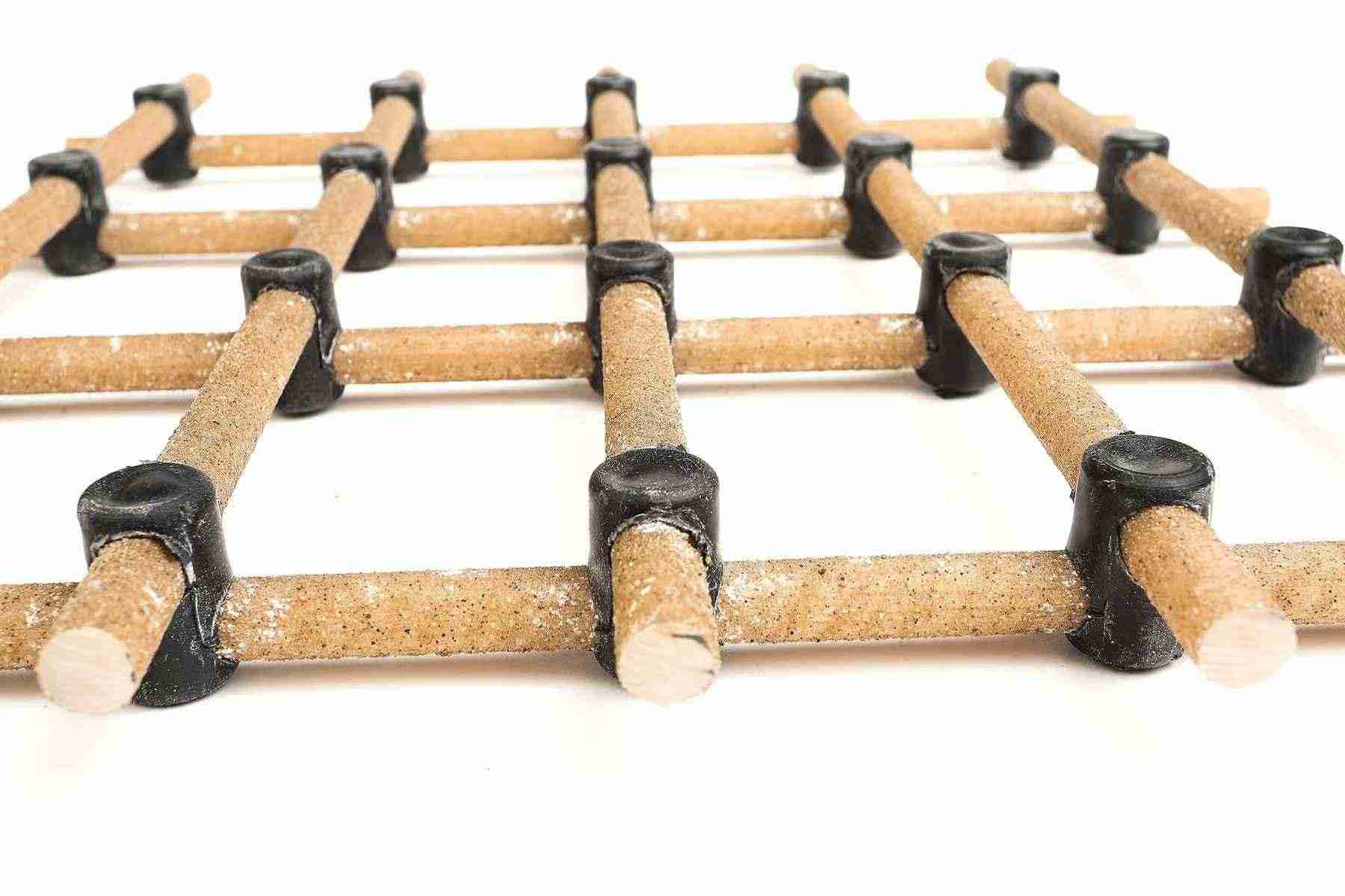
Professional GFRP rebar grid installation showing proper spacing and non-metallic support systems
Your GFRP rebar project isn’t truly non-corrosive if you’re using steel tie wire. A single metal chair or ferrous coupler compromises the corrosion immunity and electromagnetic neutrality you paid for. Here’s the complete accessory specification guide for code-compliant GFRP systems.
Section 1: Why Your Accessory Selection Determines System Success
The Critical Specification Gap
You’ve specified GFRP rebar for corrosion immunity or electromagnetic neutrality. Your bars won’t rust and won’t conduct electricity—but what about your accessories?
A steel tie wire will rust. It expands, cracks the concrete cover, and creates the exact corrosion point you’re trying to eliminate.
A metal support chair will corrode. Even epoxy-coated, a single scratch exposes the steel substrate to chloride attack.
A ferrous coupler introduces EMI. In an MRI facility or sensitive monitoring system, it acts as an antenna, defeating your electromagnetic neutrality requirement.

Steel reinforcement corrosion creates expansive forces that crack concrete—the exact failure mode dielectric accessories prevent
This is why ACI 440.5 Section 2.1.3 mandates: all permanent reinforcement supports must be made of dielectric material (non-metallic, non-conductive).
What “Dielectric Accessories” Actually Means
The ACI committee’s specific word choice—”dielectric”—is deliberate. A dielectric accessory is:
- Non-metallic → Cannot corrode
- Non-conductive → Preserves electromagnetic neutrality
This single specification automatically enforces both primary benefits of your GFRP system.
The Accessory Categories You Must Specify
Your complete GFRP accessory system requires specifications for five categories:
- Positioning Systems (chairs, spacers, bolsters) → Maintain concrete cover
- Fastening Solutions (ties, clips) → Secure bar intersections
- Continuity Systems (couplers) → Join bar lengths
- Safety Devices (end caps) → OSHA impalement protection
- Installation Tools → Field cutting and placement equipment
This guide provides technical specifications for each category to meet ACI 440.5 requirements.
Section 2: Governing Standards for Accessory Specification
The Mandatory Code: ACI 440.5-08
While ACI 440.11-22 governs your structural design and ASTM D7957 governs the bars themselves, accessories are governed by ACI 440.5-08: Specification for Construction with Fiber-Reinforced Polymer Reinforcing Bars.
The critical requirement—ACI 440.5 Section 2.1.3:
“Use reinforcement supports made of dielectric material or, if ferrous, coated with dielectric material, including epoxy or another polymer.”
Why You Should Exceed the Minimum
ACI 440.5 technically allows “ferrous supports coated with dielectric material” as a minimum compliance threshold. This is not best practice.
Coated steel represents a single-point failure mode:
- Field damage during installation scratches the coating
- Concrete placement abrasion wears through the coating
- Thermal cycling causes coating delamination
- A single defect initiates localized corrosion
Best practice specification: Mandate 100% non-ferrous, dielectric materials for all permanent structural accessories. This eliminates the coating failure mode entirely.
The Two-Category Framework
Your specification must differentiate between two distinct accessory categories:
Category A: Permanent Structural Accessories
- Chairs, spacers, ties, couplers
- Remain embedded in concrete
- Requirement: 100% dielectric, non-ferrous materials
Category B: Temporary Safety Accessories
- Impalement-rated end caps
- Removed before concrete placement
- Requirement: OSHA-compliant (may contain steel core for structural performance)
This framework resolves the apparent contradiction between the non-metallic system mandate and OSHA safety requirements.
Section 3: Positioning Systems (Chairs, Spacers, and Bolsters)
Function and ACI Requirements
Positioning accessories maintain your specified concrete cover—the distance between reinforcement and concrete surface. All supports must be ACI-compliant dielectric materials to avoid compromising your non-corrosive, non-conductive system.

Steel rebar (left) versus GFRP rebar (right): corrosion vulnerability versus corrosion immunity
Material Specifications: Why Plastics Are Superior
Chemical Resistance:
Plastic support chairs (typically polypropylene or polycarbonate) are impervious to:
- Concrete’s alkaline environment (pH 12-13)
- De-icing salt chlorides
- Marine salt exposure
- Industrial chemical attacks
Thermal Compatibility:
Unlike steel, polypropylene has a coefficient of thermal expansion compatible with concrete. This prevents the differential expansion stresses that cause concrete cracking at support points.
Commercial Products: Technical Specifications
Dayton Superior Aztec Series:
Aztec Castle Chair® (PCC)
- Material: Dark recycled plastic
- Classification: CRSI Class 1 Bar Support
- Load capacity: Average >600 lbs at room temperature
- Sizes: Various heights from 3/4″ to 6″
- Temperature rating: Suitable for concrete curing temperatures
Aztec Tower Chair™ (PTC)
- Material: Composite one-piece base
- Design: Height-adjustable inserts
- Application: Variable slab thickness requirements
Blackthorn, LLC Plastic Spacers:
Material: Recycled Polypropylene (Hostalen GC 7260)
- Tensile Yield Strength: 4,060 psi (28 MPa)
- Deflection Temperature: 248°F at 264 psi
- Chemical resistance: Excellent in alkaline environment
- UV resistance: Suitable for extended field exposure
The Critical GFRP-Specific Requirement: Buoyancy Control
Here’s where steel-based specifications fail for GFRP.
GFRP density is approximately 2.0 g/cm³ compared to steel’s 7.8 g/cm³—making it 75% lighter. During concrete placement, high-flow concrete exerts significant buoyant force on the low-density reinforcement grid. Without proper anchoring, the grid floats upward, destroying your concrete cover specification.
The Spacing Solution:
Support chairs for GFRP require significantly tighter spacing than for steel:
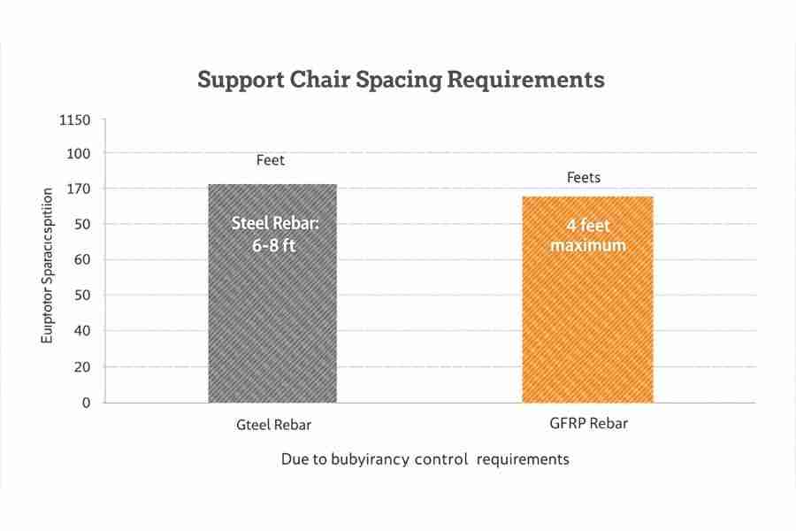
Critical spacing difference: GFRP requires maximum 4-ft spacing versus 6-8 ft for steel
| Reinforcement Type | Maximum Support Spacing |
|---|---|
| Steel rebar | 6-8 feet on center |
| GFRP rebar | 4 feet on center maximum |
Technical guides specify: “Support chairs are required at two-thirds the spacing of steel rebar.”
Design Philosophy Inversion:
Traditional bar chairs are compressive supports (holding the grid up). GFRP chairs must also function as anchors (holding the grid down). Modern plastic chairs feature:
- Firm locking mechanisms
- Cavity designs that fill with concrete
- Rebar retention systems preventing vertical displacement
This represents a complete inversion of traditional support chair function.

ACI 440.5 compliant plastic mesh chairs provide dielectric support for GFRP reinforcement grids
Specification Language for Positioning Systems
REINFORCEMENT SUPPORT SYSTEMS:

1. Material: 100% non-ferrous, dielectric material. Steel supports
   (including coated steel) are not permitted.

2. Products: Plastic or composite chairs conforming to CRSI
   classifications. Acceptable manufacturers: Dayton Superior Aztec
   Series, Blackthorn LLC, or approved equal.

3. Spacing: Maximum 4 feet on center in both directions for horizontal
   reinforcement. Reduce to 3 feet on center in areas with bar
   congestion or as required to prevent flotation during concrete
   placement.

4. Load Rating: Minimum 500 lbs capacity at anticipated concrete
   placement temperature.

5. Installation: Chairs shall provide positive retention of GFRP bars
   against buoyant forces during concrete placement.
Section 4: Fastening and Securing Solutions (Ties and Clips)
ACI Dielectric Requirements for Fasteners
To secure GFRP bar intersections and form a rigid grid, all fasteners must be non-metallic per ACI 440.5.
Approved materials:
- Nylon zip ties
- Polycarbonate clips
- Composite ties
- High-quality plastic fastening systems
Explicitly prohibited: Standard steel tie wire. This is the most common specification violation and completely compromises your enhanced system.
Professional comparison of steel versus fiberglass rebar installation and testing (Matt Risinger, 12:14)
GFRP-Specific Fastening Challenges
Challenge #1: Surface Damage Vulnerability
GFRP is anisotropic—strong along its fiber axis but vulnerable to transverse damage. Field reports document: “They tie GFRP like steel and wonder why bars crack.”
Over-tightening any fastener (especially metal wire) creates surface notching:
- Concentrates stress at the notch
- Initiates micro-cracking in the resin matrix
- Reduces bar tensile capacity by 15-30%
Installation requirement: Controlled tying pressure to prevent surface damage.
Challenge #2: Grid Rigidity and “Wracking”
GFRP has a modulus of elasticity of 40-60 GPa compared to steel’s 200 GPa—it’s more flexible. Simple zip ties provide minimal lateral stiffness. The grid can “wrack” (move and deform) during:
- Worker foot traffic
- Concrete placement
- Form vibration
This threatens your specified bar positions and concrete cover.
Solution 1: Traditional Plastic Zip Ties
Advantages:
- Fully ACI-compliant (100% dielectric)
- Non-damaging to bar surface
- Low cost per unit
- Widely available
Disadvantages:
- Slow manual installation (labor-intensive)
- Very low grid rigidity (high wracking susceptibility)
- No tooling for high-speed installation
- Requires careful tension control
Best application: Small projects or areas with minimal traffic
Solution 2: Engineered Polycarbonate Clip Systems
A new generation of fasteners solves both speed and rigidity problems while maintaining ACI compliance.
Kodi Klip System (Dayton Superior):
Material Specifications:
- Non-rusting polycarbonate
- High-impact resistant
- Heat-resistant dielectric material
- Temperature range: -40°F to 180°F
Installation Systems:
- Pneumatic Klipper Gun (air-powered)
- Battery Powered Klipper (cordless)
- Application speed: 3-5 seconds per connection
Performance Characteristics:
- Rigid 4-point grip design
- Dramatically reduces grid wracking (60-80% improvement vs zip ties)
- Compatible bar sizes: #3 through #6
- Compatible materials: Steel, basalt, FRP rebar
Kodi Klip rebar connecting system installation demonstration showing speed and 4-point grip (2:13)
Encore Snappers Fasteners:
Material: Polycarbonate construction
Installation:
- Air Snapper™ Pneumatic Tool
- Manual tool options available
Compatibility:
- Bar sizes: #3 and #4
- Materials: Steel, FRP, basalt rebar
Cost-Benefit Analysis: Labor vs. Materials
| Factor | Zip Ties | Polycarbonate Clips |
|---|---|---|
| Material cost/unit | $0.02-0.05 | $0.15-0.30 |
| Installation time | 15-20 sec | 3-5 sec |
| Tool required | None | $800-1,500 |
| Grid rigidity | Low (high wracking) | High (minimal wracking) |
| Labor cost/1000 ties | $280-375 | $85-140 |
Break-even analysis: For projects requiring >5,000 connections, polycarbonate clip systems provide lower total installed cost despite higher material unit costs.
Three-Factor Optimization
Engineered polycarbonate clips are the only solution optimizing all critical factors simultaneously:
- ACI Compliance: 100% dielectric material
- Installation Speed: Pneumatic/battery tool application
- Structural Performance: High-rigidity, anti-wracking grid
Specification Language for Fastening Systems
REINFORCEMENT FASTENING SYSTEMS:

1. Material: 100% non-ferrous, dielectric material. Steel tie wire
   is not permitted under any circumstances.

2. Approved Options:
   a) Polycarbonate clip systems (Kodi Klip, Encore Snappers, or equal)
   b) Nylon cable ties (UV-resistant, min. 50 lb tensile strength)

3. Installation Requirements:
   a) Tying pressure shall not damage bar surface or create notching
   b) Grid shall demonstrate minimal movement under foot traffic
   c) All intersections at perimeter and at 24" o.c. maximum shall
      be tied

4. Quality Control: Inspector shall verify no surface damage at tied
   locations before concrete placement approval.
Section 5: Structural Continuity Systems (Mechanical Couplers)
Why Couplers Are Essential for GFRP
GFRP cannot be bent on-site. This is non-negotiable. The material is a thermoset composite—any attempt at field bending causes internal micro-fractures, compromising structural integrity.
All bends, hooks, and stirrups must be factory-manufactured. For straight bar-to-bar connections where lap splices are impractical, mechanical couplers are your only option.
When couplers are required:
- Bar continuity in congested areas (lap splices impractical)
- Large-diameter bars (>No. 10) where ACI 440.1R prohibits lap splices
- Precast segmental construction joints
- Vertical column/wall continuity between floors
The Critical Performance Gap: Coupler Failure Data
This is your system’s most critical weak link.
The anisotropic nature of GFRP creates an immense engineering challenge: the bar is strong longitudinally (600-1,740 MPa) but weaker in transverse shear. Gripping the bar to transfer 100% of its tensile load without causing shear failure is extremely difficult.
Alarming test data from independent testing (2019):

Critical failure data: Some GFRP couplers fail at only 14-18% of bar capacity—your system’s weakest link
| Connection Type | Failure Load | Achieved Stress | % of Bar Capacity | Failure Location |
|---|---|---|---|---|
| GFRP Bar Only (control) | 33.7 kips | 145 ksi | 100% | Grips (bar stronger) |
| GFRP + Epoxy Coupler | 6.0 kips | 25.8 ksi | 18% | Connection |
| GFRP + 8-Bolt FRP Coupler | 4.7 kips | 20.2 ksi | 14% | Connection |
In this test series, couplers failed at 14-18% of the bar’s demonstrated capacity. This isn’t a splice—it’s a structural failure point.
This doesn’t mean all couplers are deficient. Other manufacturers’ pull tests have demonstrated proper performance with no premature failure. The vast performance discrepancy illustrates what ACI 440.1R explicitly acknowledges as a “Knowledge Gap”: technology for manufacturing high-strength GFRP bars has outpaced the technology for reliably connecting them.
Critical specification principle: Your system’s true strength isn’t the bar’s advertised 145 ksi—it’s potentially the 20.2 ksi of the weakest coupler, unless rigorously proven otherwise through testing.
Coupler Types and Selection Criteria
Mechanical Threaded Couplers:
- Bar ends machined with threads
- Coupler sleeve with internal threads
- Load transfer through mechanical engagement
- Advantage: Proven technology, visual inspection possible
- Disadvantage: Requires precise thread machining
Adhesive Bonded Couplers:
- Epoxy or vinyl ester resin bonds
- Requires surface preparation and curing time
- Advantage: Can achieve good bond strength
- Disadvantage: Quality control difficult, environmental sensitivity
Sleeve + Grip Couplers:
- Mechanical gripping wedges inside sleeve
- Various proprietary designs
- Advantage: No bar-end machining required
- Disadvantage: Performance highly variable by manufacturer
Performance-Based Specification Requirements
You cannot write “GFRP coupler” and assume performance. You must specify:
Minimum Performance Standard:
"Coupler system shall develop minimum 125% of the bar's guaranteed
tensile strength per ASTM D7957, as demonstrated by manufacturer's
test reports."
Required Submittals (before approval):
- Material Test Certificates (MTCs)
- Certifying coupler material properties
- Batch traceability
- Manufacturer’s Installation Manual
- Step-by-step procedures
- Torque specifications
- Alignment tolerances
- Type Test Reports
- Minimum 5 specimens tested to failure
- Test method: ASTM D7913 or equivalent
- Results showing failure load and failure mode
- Mock-up or Trial Splice Tests
- Performed with actual project bars
- Witnessed by engineer or inspector
- Documented with photographs and data
Installation Quality Assurance Protocol
Pre-installation:
- [ ] Verify coupler size matches bar size
- [ ] Inspect bar ends (square cut, no damage, clean)
- [ ] Check coupler threads (no damage, debris removed)
During installation:
- [ ] Verify proper bar alignment (within 1° of straight)
- [ ] Confirm full thread engagement (visual check)
- [ ] Apply specified torque (calibrated torque wrench)
- [ ] Document torque values for each coupler
Post-installation:
- [ ] Visual inspection of alignment
- [ ] Verify no bar surface damage near coupler
- [ ] Photograph all couplers before concrete placement
- [ ] Maintain installation records
Specification Language for Couplers
GFRP REBAR COUPLERS:

1. Performance Requirement: Coupler system shall develop minimum
   125% of the bar's guaranteed tensile strength per ASTM D7957.

2. Submittals Required:
   a) Material test certificates (MTCs)
   b) Manufacturer's installation manual with torque specifications
   c) Type test reports (minimum 5 specimens, showing failure mode)
   d) Mock-up splice test reports using project bars

3. Installation Requirements:
   a) Bar alignment within 1° of straight
   b) Full thread engagement verified visually
   c) Torque applied per manufacturer specifications (calibrated wrench)
   d) Each coupler documented with unique identifier and torque value

4. Quality Control: Engineer reserves right to require field pull
   tests of random couplers (minimum 2% of total, or 3 couplers,
   whichever is greater).

5. Field Bending: Field bending of GFRP bars is prohibited. All
   bends, hooks, and stirrups shall be factory-manufactured.
Section 6: Jobsite Safety Systems (Rebar End Caps)
OSHA Requirement: 29 CFR 1926.701(b)
Protruding rebar poses impalement hazards from falls. OSHA mandates:
“All protruding reinforcing steel, onto and into which employees could fall, shall be guarded to eliminate the hazard of impalement.”
The Critical Distinction: Two Entirely Different Products
This is the most common—and dangerous—specification misunderstanding.

OSHA-compliant steel-reinforced impalement protection caps—only these meet 29 CFR 1926.701(b) requirements
Product Type 1: Mushroom Caps (Scratch Protection)
- Small plastic caps
- Soft, flexible material
- Purpose: Prevent skin scratches and torn clothing
- OSHA Compliant for Impalement? NO
Product Type 2: Impalement-Rated Safety Caps
- Plastic shell with internal steel reinforcement
- Contains heavy-duty steel cup (typically 3/16″ steel)
- Purpose: Prevent penetration during falls
- OSHA Compliant for Impalement? YES
The 1997 OSHA Clarification Memo
A critical 1997 OSHA memorandum explicitly addressed this distinction:
California OSHA Drop Tests:
- Test: 140-160 lb sandbags dropped from 3 feet
- Mushroom caps: Provided “absolutely NO protection” against impalement
- Bars penetrated through the caps in every test
Manufacturer Statements:
Manufacturers confirmed mushroom caps are designed for “SCRATCH PROTECTION ONLY” and were “never intended to prevent impalement.”
Compliance Conclusion:
Mushroom caps do not meet 29 CFR 1926.701(b) requirement to “eliminate the hazard of impalement.”
Performance Specifications for Compliant Caps
Impalement-rated safety caps specifications:
Structural Design:
- External: High-impact plastic shell (polycarbonate or HDPE)
- Internal: Steel reinforcement cup (minimum 3/16″ thickness)
- Base: Wide footprint to distribute impact force
Performance Rating:
- Must withstand 250-pound drop from 7.5 feet
- Based on Cal/OSHA testing criteria
- No bar penetration through cap after impact
Visual Identification:
- Bright safety colors (orange, yellow)
- Often labeled “OSHA Compliant” or “Impalement Protection”
Resolving the Non-Metallic System Paradox
Apparent contradiction: Your project mandate is 100% non-metallic, yet OSHA-compliant caps contain steel cores.
Resolution—Two-Category Framework:
Category A: Permanent Structural Accessories
- Chairs, ties, spacers, couplers
- Embedded in concrete permanently
- Requirement: 100% dielectric, non-ferrous
Category B: Temporary Safety Accessories
- Impalement-rated end caps
- Removed before concrete placement
- Requirement: OSHA-compliant (steel core acceptable)
The steel-reinforced cap is a temporary safety device, not a structural component. It doesn’t compromise the corrosion-free or EMI-neutral properties of your final structure because it’s removed before the pour.
Specification Language for Safety Caps
REBAR END PROTECTION:

1. Impalement Protection: All vertical and angled protruding
   reinforcement (onto which workers could fall) shall be protected
   with impalement-rated safety caps meeting OSHA 29 CFR 1926.701(b).

2. Performance Requirement: Caps shall be rated for minimum
   250-pound drop from 7.5 feet without bar penetration.

3. Acceptable Products: Steel-reinforced safety caps. Mushroom-style
   plastic caps (scratch protection only) are not acceptable for
   impalement protection.

4. Temporary Use: Safety caps are temporary protective devices and
   shall be removed before concrete placement.

5. Color: Bright safety orange or yellow for visibility.
Section 7: Field-Validated Accessory Specifications
Case Study 1: Thetford Mines WWTP—Complete System Specification
Project: World’s first RC water chlorination tank totally reinforced with GFRP bars (Thetford Mines, Quebec)
Challenge: Severe corrosion environment from chlorine treatment chemicals
Accessory Specifications Implemented:
Positioning Systems:
- Continuous plastic chairs (perimeter support)
- Single plastic chairs (field support)
- Spacing: 36 inches on center (vs typical 72″ for steel)
Fastening Systems:
- Nylon zip ties (all bar intersections)
- Pre-tensioned to prevent wracking during placement
Quality Control:
- Fiber-optic sensors (FOS) embedded for structural health monitoring
- Real-time strain and temperature data collection
Performance Outcome (6+ Years):
- Zero corrosion at any support points
- Zero spalling or cracking related to accessories
- Fiber-optic system continues providing structural data
- Validated “maintenance-free” specification
Key Specification Insight: Steel chairs would have created discrete corrosion points within the tank, defeating the GFRP investment. The 100% dielectric accessory system was essential to achieving the design goal.
Case Study 2: Hospital MRI Facility—EMI-Critical Application
Project: Johns Hopkins Hospital MRI suite foundation and walls
Challenge: Complete electromagnetic neutrality required (steel accessories would create imaging artifacts)
Accessory Specifications Implemented:
System Mandate:
- Zero ferrous materials in entire reinforcement cage
- Single steel component would act as antenna/magnetic contaminant
Positioning Systems:
- All-plastic support chairs
- Non-metallic spacers at formwork interfaces
Fastening Systems:
- Polycarbonate clips (no metal tie wire)
- Verified non-conductive at every intersection
Performance Outcome:
- MRI equipment operational at full sensitivity
- No electromagnetic interference detected
- No imaging artifacts from reinforcement system
Key Specification Insight: Even a single metal tie wire would have compromised the $2M+ MRI equipment investment. The specification’s prohibition on “ferrous, coated” accessories (which ACI allows as minimum) was critical.
Case Study 3: Golden Gate Bridge Retrofit—Infrastructure EMI Elimination
Project: 2018 seismic retrofit, reinforcing pylons and deck structures
Challenge: Sensitive toll collection and traffic monitoring systems require EMI-free environment
Accessory Specifications Implemented:
Selection Driver:
- Electromagnetic neutrality to prevent interference with monitoring systems
Accessory Requirements:
- 100% dielectric support systems
- Non-conductive fastening throughout
- Pre-assembled cages to minimize field connections
Performance Outcome:
- Traffic monitoring systems operate without interference
- Toll collection accuracy maintained
- No signal degradation in RF transmission systems
Key Specification Insight: Steel accessories would have created antenna effects, interfering with the very infrastructure systems the bridge relies on for operation.
Section 8: Complete Specification Framework and Checklist
The Specification Cascade: Five Connected Decisions
Your GFRP accessory specification follows an interconnected decision chain:
Decision 1: Material Mandate
→ All permanent accessories: 100% non-ferrous, dielectric material
→ Exceeds ACI 440.5 minimum (no “coated steel” option)
Decision 2: Positioning Specifications
→ Spacing: Maximum 4 feet on center (not 6-8 ft used for steel)
→ Addresses buoyancy: chairs function as anchors, not just supports
→ Products: Plastic/composite chairs (Dayton Superior, Blackthorn, or equal)
Decision 3: Fastening Specifications
→ Polycarbonate clip systems preferred (speed + rigidity)
→ Alternative: Nylon zip ties (ACI-compliant but slower)
→ Prohibited: Steel tie wire under any circumstances
Decision 4: Coupler Specifications
→ Performance-based: Minimum 125% bar tensile strength
→ Submittals required: MTCs, test reports, installation manual
→ Mock-up tests required before approval
Decision 5: Safety Specifications
→ Impalement protection: Steel-reinforced caps (OSHA-compliant)
→ Scratch protection: Mushroom caps (not OSHA-compliant for falls)
→ Temporary devices: Removed before concrete placement
Master Specification Checklist
GENERAL REQUIREMENTS
- [ ] Design per ACI 440.11-22; construction per ACI 440.5
- [ ] All GFRP rebar certified to ASTM D7957 with MTCs
- [ ] Pre-construction meeting covers accessory requirements
- [ ] Inspector trained on GFRP-specific installation requirements
POSITIONING SYSTEMS (Chairs/Spacers/Bolsters)
- [ ] Material: 100% non-ferrous, dielectric (coated steel prohibited)
- [ ] Product submittals approved (Dayton Superior Aztec, Blackthorn, or equal)
- [ ] Spacing specified: Maximum 4 feet on center (both directions)
- [ ] Load rating verified: Minimum 500 lbs at placement temperature
- [ ] Installation: Positive retention against buoyancy forces
- [ ] Quality control: Verify spacing before concrete approval
FASTENING SYSTEMS (Ties/Clips)
- [ ] Material: 100% non-ferrous, dielectric (steel wire prohibited)
- [ ] System selected: Polycarbonate clips OR nylon zip ties
- [ ] If clips: Tool specified (Kodi Klip Klipper Gun or equal)
- [ ] Installation pressure: Controlled to prevent bar surface damage
- [ ] Grid rigidity: Verified (minimal movement under foot traffic)
- [ ] Tying pattern: All perimeter intersections + 24″ o.c. maximum
- [ ] Quality control: Inspector verifies no surface damage at ties
CONTINUITY SYSTEMS (Couplers)
- [ ] Performance spec: Minimum 125% bar tensile strength
- [ ] Submittals received and approved:
- [ ] Material test certificates (MTCs)
- [ ] Manufacturer’s installation manual
- [ ] Type test reports (minimum 5 specimens)
- [ ] Mock-up splice test reports
- [ ] Field bending prohibited in specification
- [ ] All bends factory-manufactured (shop drawings approved)
- [ ] Installation requirements specified:
- [ ] Bar alignment: Within 1° of straight
- [ ] Thread engagement: Full, verified visually
- [ ] Torque: Per manufacturer spec, calibrated wrench
- [ ] Documentation: Unique ID and torque value per coupler
- [ ] Quality control: Field pull tests (2% or 3 min, whichever greater)
SAFETY SYSTEMS (End Caps)
- [ ] Impalement protection specified for all protruding bars
- [ ] Performance requirement: 250 lb / 7.5 ft drop rating
- [ ] Product: Steel-reinforced caps (mushroom caps prohibited for impalement)
- [ ] Temporary use: Removal required before concrete placement
- [ ] Color: Bright safety orange or yellow
- [ ] Scratch protection: Mushroom caps acceptable for horizontal bars (non-fall areas)
INSTALLATION QUALITY CONTROL
- [ ] Pre-pour inspection protocol established
- [ ] Concrete cover verification (cover meter if needed)
- [ ] Bar position verification before placement
- [ ] Photographic documentation of critical areas
- [ ] Coupler installation records maintained
- [ ] Non-conformance reporting procedure established
CONTRACTOR QUALIFICATIONS
- [ ] Previous GFRP installation experience (references provided)
- [ ] Crew training completed on GFRP-specific requirements
- [ ] Understanding of buoyancy control requirements
- [ ] Familiarity with polycarbonate clip tools (if specified)
- [ ] Awareness of “no field bending” limitation
Frequently Asked Questions (FAQ)
Can I use my existing steel tie wire with GFRP rebar?
No. Steel tie wire violates ACI 440.5 Section 2.1.3 and is the most common specification error. It introduces corrosion points and electromagnetic interference, defeating the purpose of your GFRP system. Use nylon zip ties or polycarbonate clip systems instead.
Why do I need different chair spacing for GFRP vs. steel rebar?
GFRP’s low density (2.0 g/cm³ vs steel’s 7.8 g/cm³) creates buoyancy during concrete placement. The grid floats upward if not properly anchored. Maximum 4-ft spacing (vs 6-8 ft for steel) provides the necessary anchoring force to maintain concrete cover.
Are all GFRP couplers created equal?
Absolutely not. Test data shows some couplers fail at only 14-18% of bar capacity—this is your system’s weakest link. Never specify “GFRP coupler” generically. Demand performance-based specifications (minimum 125% bar strength) and require test reports, MTCs, and mock-up splice tests before approval.
Can GFRP rebar be bent on-site like steel?
Never. GFRP is a thermoset composite that suffers irreversible internal micro-fractures if field-bent. All bends, stirrups, and hooks must be factory-manufactured. This requires precise design and advance ordering—you cannot make field adjustments.
What’s the difference between rebar caps for scratch protection and impalement protection?
Mushroom-style plastic caps provide scratch protection only and are NOT OSHA-compliant for impalement per 29 CFR 1926.701(b). Cal/OSHA tests showed they provided “absolutely NO protection” against falls. Compliant caps must be steel-reinforced, rated for 250 lb drops from 7.5 feet. This steel component is acceptable because it’s temporary (removed before concrete placement).
Does using coated steel accessories meet ACI requirements?
Technically yes—ACI 440.5 allows “ferrous, coated with dielectric material” as minimum compliance. However, this is not best practice. Coating scratches during installation, abrasion during placement, or thermal cycling creates corrosion initiation points. Specify 100% non-ferrous dielectric accessories to eliminate this failure mode.
How much more do GFRP-compatible accessories cost compared to steel accessories?
Material costs are 20-40% higher. However, total installed costs are often comparable due to faster installation (lighter weight, pneumatic clip tools vs manual tying). More importantly, life-cycle costs are substantially lower—GFRP accessories eliminate 100% of corrosion-related repairs over 100-year design life.
Why does my GFRP grid keep moving during concrete placement?
This indicates insufficient support spacing (needs max 4-ft centers) or inadequate fastening rigidity. GFRP’s lower modulus (40-60 GPa vs steel’s 200 GPa) makes grids susceptible to “wracking” with simple zip ties. Solution: tighter spacing + polycarbonate clip systems providing high-rigidity connections.
Can I get factory-bent GFRP stirrups in custom configurations?
Yes, but order well in advance. All GFRP bends require factory manufacturing using controlled heating and forming. Work with your supplier early in design to specify custom configurations. Lead times are longer than steel fabrication (typically 4-6 weeks vs 1-2 weeks for steel).
What certification should I verify for GFRP accessories?
For bars: ASTM D7957 certification with MTCs. For positioning accessories: Verify ACI 440.5 §2.1.3 dielectric compliance. For couplers: Demand test reports showing minimum 125% bar tensile capacity. For safety caps: Verify OSHA 29 CFR 1926.701(b) compliance with 250 lb / 7.5-ft drop rating and steel reinforcement.
Should I allow “ferrous, coated” accessories to reduce costs?
Not recommended. While ACI 440.5 allows this as minimum compliance, coatings represent single-point failures. Field damage, placement abrasion, or thermal cycling compromises the coating, initiating localized corrosion. The cost savings are minimal compared to the risk of creating the exact failure points you’re trying to eliminate. Specify 100% non-ferrous accessories.
How do I verify my contractor understands GFRP accessory requirements?
Pre-construction meeting checklist: (1) Demonstrate understanding of buoyancy control and 4-ft spacing requirement, (2) Acknowledge no field bending limitation, (3) If using polycarbonate clips, show familiarity with pneumatic tools, (4) Verify they understand steel tie wire prohibition, (5) Request references from previous GFRP projects with similar accessories.
Conclusion: Accessories Determine System Success
Your GFRP rebar investment delivers corrosion immunity, electromagnetic neutrality, and extended service life—but only when every accessory meets the dielectric mandate.
The three critical specification principles:
- 100% Dielectric for Permanent Components
Exceed ACI minimum by prohibiting “ferrous, coated” accessories. Specify 100% non-ferrous materials for chairs, ties, spacers, and couplers.
- GFRP-Specific Installation Requirements
Address buoyancy (4-ft max spacing), surface damage vulnerability (controlled tying pressure), and no field bending (factory-manufactured shapes only).
- Performance-Based Coupler Specifications
Never specify “GFRP coupler” generically. Demand 125% bar strength with test reports, MTCs, and mock-up splices. This is your weakest link.
The case studies prove the principle: in Thetford Mines, steel chairs would have created corrosion points. At Johns Hopkins, metal tie wire would have compromised the MRI equipment. On the Golden Gate Bridge, ferrous accessories would have interfered with monitoring systems.
Your specification checklist ensures:
- Code compliance (ACI 440.5, OSHA 29 CFR 1926.701)
- Material performance (dielectric, corrosion-immune)
- Installation quality (proper spacing, no surface damage)
- System integrity (electromagnetic neutrality maintained)
Use the master checklist provided to write specifications that deliver genuine, long-term structural performance from your GFRP reinforcement system.
For project-specific accessory specifications, consult with structural engineers experienced in GFRP-reinforced concrete. Verify all product submittals against ACI 440.5 requirements before approval.
Request a B2B Manufacturing Quote – Share your profile, rebar, machine, or die requirements and we will return specifications, lead time, and export pricing. Contact IncomePultrusion for a project quote.
Standards Referenced in This Guide
- ASTM D7957/D7957M-22 — Standard Specification for Solid Round Glass Fiber Reinforced Polymer Bars for Concrete Reinforcement.
- ACI PRC-440.1-15 — Guide for the Design and Construction of Structural Concrete Reinforced with FRP Bars (ACI Committee 440).

